Automatic Fishing Stick is a simple DIY project using PIC microcontroller. It performs fishing in an automated way. Anyone can try out this DIY project at their home, by using the easily available electronic components like PIC microcontroller, motor driver IC, a simple gear motor and LEDs.
Using START, END, LINE UP, LINE DOWN switches, this Automatic Fishing Stick DIY project gives you the best ever fishing experience. Compared to manual fishing system, features like accuracy, better control, less man power and energy consumption makes Automatic Fishing Stick outstanding. In extent, more efficiency can be achieved by attaching increased number of fishing lines to the DIY project; thereby grabing more fishes at a time.
Hence, its time to Practice fishing in an automated way & make your fishing experience simple and attractive using this DIY project……

Block Diagram of Automatic Fishing Stick
The block diagram of this DIY project consists of:

Automatic Fishing Stick
There are basically four switches in this DIY project. They are FISHING START BUTTON, FISHING END BUTTON, FISHING LINE UP BUTTON, FISHING LINE DOWN BUTTON and a digital Fishing line length measuring. These four digital input pins are given to the CONTROL SECTION as shown in the block diagram of the DIY project. The major function of these inputs is to control or perform the desired way of fishing in the DIY project.
It is used to ACTIVE and then START the fishing process.
It is used to STOP the desired fishing process suddenly.
Used to set fishing line position upwards. It is under the control of the user and motor.
It is used to set the fishing line position downwards and is under the control of motor and user.
How to measure the fishing line length in this DIY project???
In this simple electronics project, to measure the length of the fishing line, we make use of the below components.
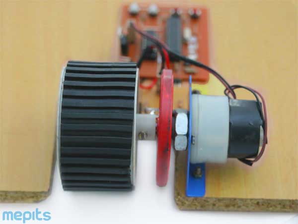
Here, the rotating disc is coupled to the fishing motor on which the fishing line is connected. The rotating disc has holes at every 1 cm. An IR Tx/Rx is placed at each side of the disc which helps to detect the holes coming in front. The IR Tx/Rx detects holes as digital input to the microcontroller.
Number of Holes x 1cm= Length of Fishing Line
PIC Microcontroller PIC16F883 acts as the Control Section of this DIY project. The main function of the CONTROL SECTION is to control the entire DIY project. Here it receives the digital inputs (Switches, Hole Detection, Speed Calculation) and gives out the digital outputs (Motor Control and LEDs). To ensure proper operation of the IC, a Vcc of 5volt is provided.
Generally, PIC16F883 is one of the modern CMOS FLASH based 8 bit, 28 pin microcontroller from Microchip. With many internal peripherals, PIC16F883 is found to be the best for this DIY project.

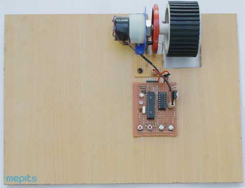
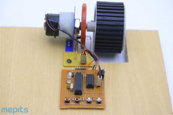
Model of Automatic Fishing Stick, DIY Project
This DIY project uses a 12volt, 750 rpm Gear Motor as the FISHING MOTOR. The main function of the motor is to perform clockwise and anti-clockwise rotation for proper controlling of FISHING LINE UP BUTTON, FISHING LINE DOWN BUTTON.
Rotation of the gear motor in clockwise direction helps the fishing line to move downwards. While its rotation in anti-clockwise direction helps the fishing line to move upwards.
Also, at the time when the fish gets hooked to the fishing stick, the line moves down. From the Rotating Disc and controller calculate the fishing line speed. And ensure the presence of fish.
Since the PIC microcontroller cannot provide the required high voltage and current to the FISHING MOTOR, we cannot directly connect the CONTROL SECTION to the FISHING MOTOR of the DIY project. So a motor driver IC is used as shown in the block diagram.
Here, in this DIY project, L293DE acts as the motor driver IC. L293DE is a 16 pin dual H bridge driver circuit, requiring a power supply of 5volt for its operation. The main purpose of using L293DE in this electronics project is that it can drive the FISHING MOTOR in clockwise and anticlockwise direction, thereby helping to do the fishing process effectively.
Now, for the indication purpose two LEDs are used in this simple electronics project. One is a RED LED and other one is a GREEN LED.
At the first press of the START Button:
At the second press of the START Button:
Note: For a better indication purpose, you guys can use a buzzer instead of the LEDs.

DIY Project
Grab your fish and repeat the entire process to gain more…. Have a great fishing day with this Automatic Fishing Stick, DIY Project…
Note: By attaching more number of fishing lines to this single Automatic Fishing Stick, better efficiency can be achieved. And at the same time, this simple electronics project helps one to reduce the work load faced by a manual fishing system.